Lux Wind Power
Background
My name is Glen Lux. I am a mechanical engineer, and I’ve designed, built and tested over 50 Vertical Axis Wind Turbines (VAWT). Some of my turbines are connected to the grid but others are built, tested and decommissioned to make room for newer designs.
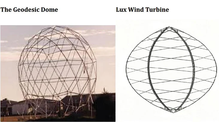
The Outside Framed Wind Turbine
My latest concept uses a frame on the outside of the VAWT instead of using guy cables or a mast fixed to the earth. Normally, long beams with a small cross section requires bracing from several directions for most applications. The following will explain why this is not necessarily the case.
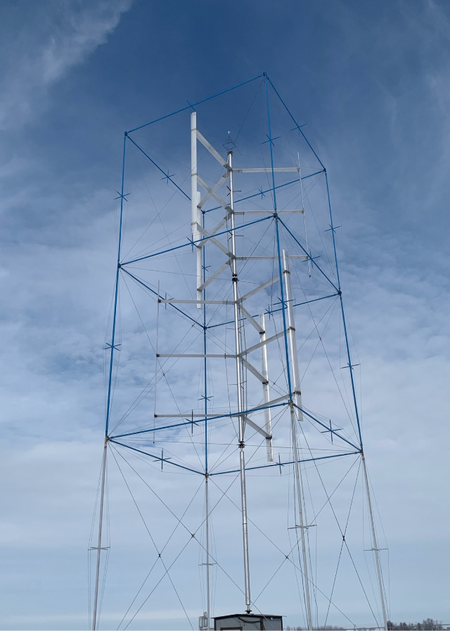
The drawing above shows 2 separate turbines, one on top of the other. The 3 Outside Frames are cubic shapes and are also stacked on top of each other. The turbines are slightly smaller than the cubic frame to allow for movement in high winds. Most straight bladed VAWT have height/diameter ratios close to 1, so I picked the cube shape for simplicity. Each cube has 4 vertical beams, 4 horizontal beams and 5 pairs of diagonal beams crossing in the middle of each side. The diagonal beams are tensioned, which causes the other beams to be in compression, even under extreme wind loads. Usually, I do not put a turbine in the bottom cube, but one can be added even if it is not the full height of the cube. The diameter of the lower turbines could be a bit smaller than the top turbine to accommodate wind shear.
The diagonal beams on the top face of each cube contain a bearing at the intersection. The bearings are the only places where the Outside Frame experiences the thrust forces from the wind.
The weight of all the masts, struts and blades is supported by the bearing at the bottom of the lowest mast. Therefore, the only major forces acting on the cubed frame are the thrust forces from the wind on each turbine and gravity from the frame above it. The ends of the horizontal and vertical beams can be considered as pinned, which prevents bending moments, torsion or shear on these beams. All vertical and horizontal beams are in compression, so column buckling needs to be analyzed.
About Column Buckling
Column buckling happens when a beam under compression suddenly deforms laterally. The critical buckling load (Pcr) is the maximum allowable force applied at each end of the beam before buckling occurs. Euler’s formula is used to predict Pcr on simple beams but cannot predict Pcr on more complicated structures.
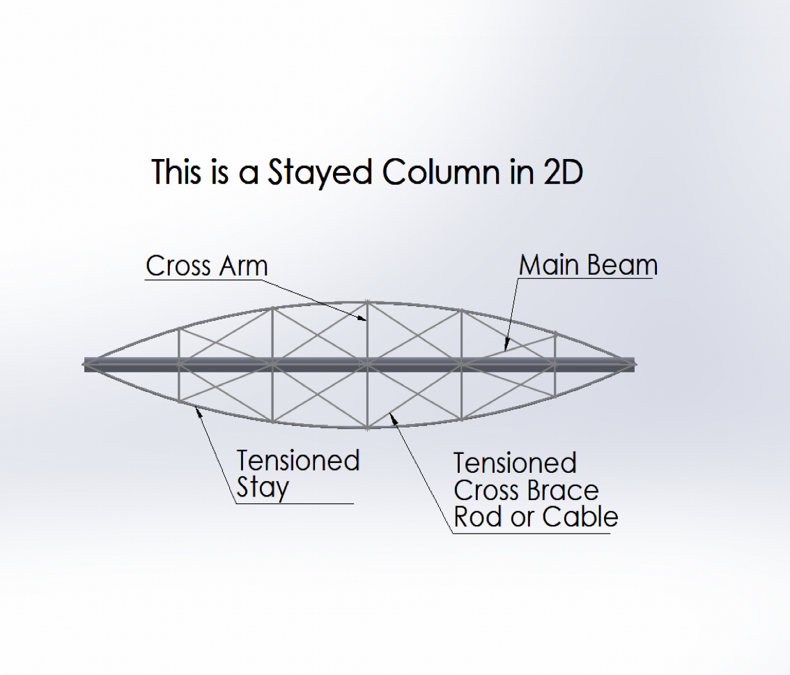
Prestressed Stayed Columns (PSSC), or just Stayed Columns, are beams with cross arms at one or more positions and stays (pretensioned cables or rods) are attached close to the ends of the beam and at the end of each cross as shown in the diagrams below.


There are many ways to increase the maximum allowable force on stayed columns. If we adjust any of the properties such as the cross section or lengths of the main beam, crosses or stays, the Pcr will change. Adding braces, in tension, between the main beam and the ends of the cross arms is an excellent way to increase Pcr without significantly increasing the weight.
To analyze the PSSC I use a numerical procedure called the Stiffness Probe Method described by German Gurfinkel and Sudarshan Krishnan.[1] The SPM uses a perturbation force and an elastic artifice spring with a nonlinear analysis. The procedure is described fully in the cited article.
I have built and tested more than a dozen stayed columns with various lengths, cross arms and bracing. The SPM provides an accurate method for calculating the critical load for almost any beam design.
Gravity becomes a bigger concern when the beams are in a horizontal position. However, the tension in the stays below the beam can be increased to overcome the gravity force and to keep the beam straight. These stays typically need to have a larger cross section due to the increased tension.
The cross arms and stays are separated by 90 degrees. To prevent interference with the blades, two cross arms are positioned vertically, and two horizontally.
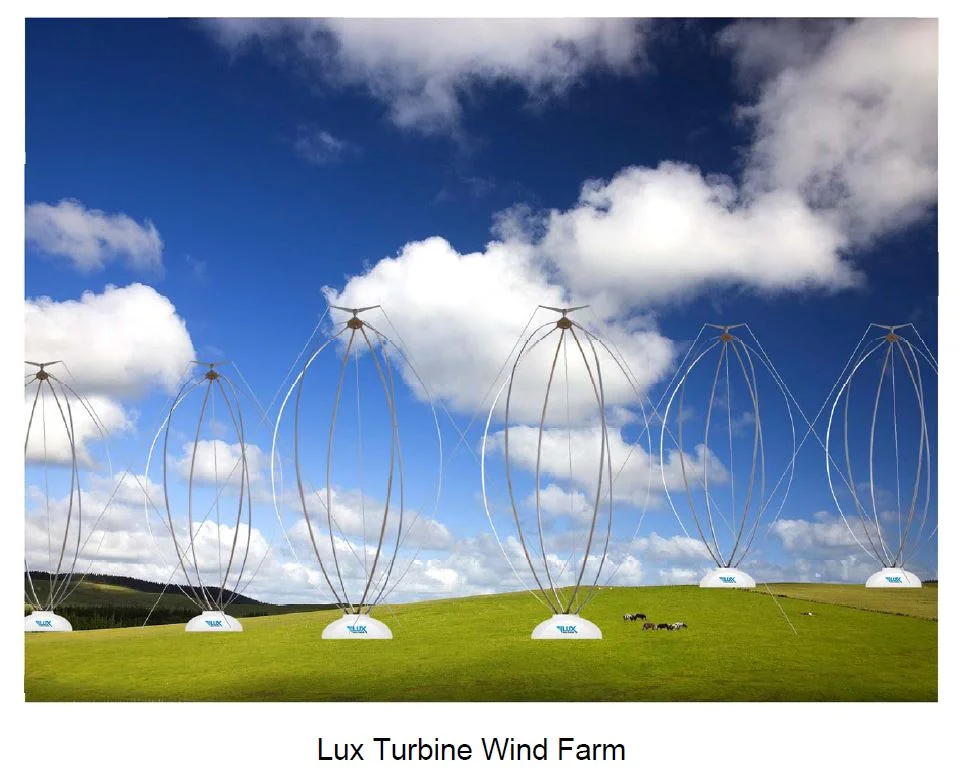
Benefits of this design
The Outside Frame enhances and preserves many of the advantages of the VAWT:
All mechanical and electrical components are on the ground: not high in the air.
The turbine does not need to be turned into the wind. It accepts wind from all directions.
Multiple stacked turbines take advantage of higher winds higher above the ground.
Multiple stacked turbines have a rotational speed similar or higher than HAWT of the same power rating. This lowers the cost of gearboxes or direct drive generators.
The blades usually have a constant profile, which make them easy to manufacture.
The Outside Frame has 4 corners that are far apart from each other, which make it a candidate for a floating wind turbine. By adding more beams at or below the water level, this structure would provide stability with little modification.
It has been demonstrated that VAWT can be spaced closer together than HAWT, because HAWT have a large wake turbulence which reduces the wind speed downstream. In some cases, the wake from several VAWT, placed strategically, can enhance the wind speed and increase power production.
Aluminum blades have the advantage of being fully recyclable.
The blades do not need pitch control. The power and speed are regulated through electrical and mechanical systems. Aerobrakes can also be installed if more control is required.
Components of the blades and frame can be built in sections for easy transportation and installation.
[1] Gurfinkel, German and Krishnan, Sudarshan. “Analysis and Design of Cable-stayed Steel Columns using the Stiffness-Probe Method,” Engineering Journal, 3rd Quarter, pp. 195-209, American Institute of Steel Construction (AISC), United States, July 2017.
Media & News